Guangdong Futian Electric Co., Ltd.


Low-Voltage Intelligent Power Capacitor Compensation Device (FTZD Type)
Product Overview:
Share:


Product Introduction
I. Product Overview.
The low-voltage intelligent power capacitor compensation device is a next-generation reactive power compensation system designed for 0.4 kV, 50 Hz low-voltage distribution networks. It delivers high efficiency and energy savings, reduces line losses, and improves the power factor and power quality. The device comprises an intelligent measurement and control unit, a synchronous switching circuit, a line protection unit, and two low-voltage power capacitors. It replaces conventional automatic reactive power compensation systems that consist of discrete components—such as fuses, composite switches or mechanical contactors, thermal relays, low-voltage power capacitors, and indicator lights—wired together inside and on the surface of the switchgear cabinet. By eliminating the bulky, unwieldy design of traditional units, this new generation of low-voltage reactive power compensators offers superior compensation performance, a more compact footprint, lower power consumption, reduced costs, greater cost‑effectiveness, enhanced flexibility in application, simplified maintenance, extended service life, and higher reliability—meeting the increasingly stringent requirements of modern power grids for reactive power compensation.
The low-voltage intelligent power capacitor compensation device is equipped with a dot-matrix LCD display that can show, in real time, the three-phase bus voltage, harmonic content of the three-phase bus voltage, frequency, the number of capacitor banks and the measured nominal values of the capacitors, the switching status of the capacitors, the current through the capacitors, and the temperature of the capacitors.
The low-voltage intelligent power capacitor compensation device employs an internal synchronous switching circuit to automatically identify the optimal switching-in (or switching-out) point, enabling arc-free make-and-break operations. It ensures zero-crossing switching, eliminates inrush currents, prevents contact welding, minimizes energy consumption, and suppresses harmonic distortion. Additionally, it features built-in protection functions against electromagnetic interference and phase-loss conditions, making it particularly well-suited for capacitor switching in reactive power compensation applications—without the need for an external heat sink.
II. Conditions of Use
| Altitude | ≤2000 meters |
| Ambient temperature | -20℃ to +60℃ |
| Relative humidity | 20% to 90% (at 40°C) |
| Atmospheric pressure | 79.5 kPa to 106 kPa |
| Environmental conditions | The surrounding medium is free from explosive hazards, non‑corrosive gases that could damage insulation or corrode metals, and conductive dust. The installation site should not be subject to severe vibrations, nor exposed to rain or snow, and the equipment is intended for indoor use. |
III. Technical Parameters
3.1 Power Supply Requirements
| Operating voltage | AC 380 V ±20% |
| Operating frequency | 50Hz |
| Voltage waveform | Sine wave, total harmonic distortion ≤ 5% |
| Power consumption | <0.5 W (when the capacitor is disconnected), <2 W (when the capacitor is connected) |
3.2 Safety Requirements
Meets the relevant requirements of GB/T 15576-2020, “Low-Voltage Complete Reactive Power Compensation Devices.”
3.3 Measurement Accuracy
| Voltage | ±0.2% |
| Electric current | ±0.2% |
| Active power | ±0.5% |
| Reactive power | ±0.5% |
| Frequency | ±0.2% |
| Power factor | ±0.5% |
3.4 Protection Error
| Voltage | ≤0.5% | Electric current | ≤1.0% |
| Temperature | ±1℃ | Time | ±0.01s |
3.5 Reactive Power Compensation Parameters
| Reactive Power Compensation Error | ≤75% of the minimum capacitor rating |
| Capacitor switching interval | >10s |
3.6 Reliability Parameters
| Control accuracy | 100% |
| Capacitor capacitance degradation rate over operating time | ≤1%/year |
| Capacitor capacity switching decay rate | ≤0.1% per ten thousand operations |
| Annual failure rate | 0.10% |
IV. Product Outline Drawing
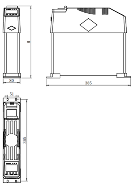
5. Product Selection Table (General Parameters) Mounting Hole Dimensions: 4–6 × 10
| Product Specifications | Switching device | System | Installation | Fundamental wave | Capacitor | External dimensions | Installation dimensions | Approximate weight |
| Voltage | Capacity | Output capacity | Rated voltage | Length × Width × Height | kilogram | |||
| kv | four | four | kv | mm | mm | |||
| FTZD-YF250(5) | Synchronizing relay | 0.22 | 5 | 4.5 | 0.25 | 385*80*250 | 365*51 | 4 |
| FTZD-YF250(10) | Synchronizing relay | 0.22 | 10 | 9 | 0.25 | 385*80*250 | 365*51 | 4 |
| FTZD-YF250(20) | Synchronizing relay | 0.22 | 20 | 18 | 0.25 | 385*80*290 | 365*51 | 5 |
| FTZD-YF250(30) | Synchronizing relay | 0.22 | 30 | 27 | 0.25 | 385*80*330 | 365*51 | 6 |
| FTZD Co-compensating Type | ||||||||
| FTZD-△F450(10+10) | Synchronizing relay | 0.4 | 20 | 15 | 0.45 | 385*80*290 | 365*51 | 5 |
| FTZD-△F450(15+10) | Synchronizing relay | 0.4 | 25 | 19.7 | 0.45 | 385*80*290 | 365*51 | 5 |
| FTZD-△F450(15+15) | Synchronizing relay | 0.4 | 30 | 23.7 | 0.45 | 385*80*290 | 365*51 | 5 |
| FTZD-△F450(20+10) | Synchronizing relay | 0.4 | 30 | 23.7 | 0.45 | 385*80*330 | 365*51 | 5.5 |
| FTZD-△F450(20+15) | Synchronizing relay | 0.4 | 35 | 27.6 | 0.45 | 385*80*330 | 365*51 | 5.5 |
| FTZD-△F450(20+20) | Synchronizing relay | 0.4 | 40 | 31.6 | 0.45 | 385*80*330 | 365*51 | 6 |
*As product dimensions may be updated, the final order shall be confirmed based on the official drawings.
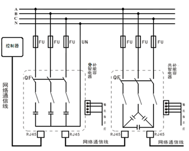
VI. Wiring configurations of the intelligent power capacitor compensation device in Δ and Y connections.
VII. Selection Guidelines (Example)
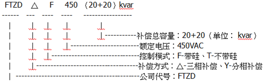
*Custom designs with varying parameters and special specifications are available upon customer request.
Download Materials
Factory Showcase


Honors and Qualifications
Product Inquiry
Get the plan
Please note: Be sure to provide accurate information and keep your contact details up to date. We will get in touch with you as soon as possible.

Telephone
Email box
Address
No. 36, Xingmin Road, Hecheng Subdistrict, Gaoming District, Foshan City
WeChat Official Account
Website Development:China Enterprise Dynamics Shunde SEO