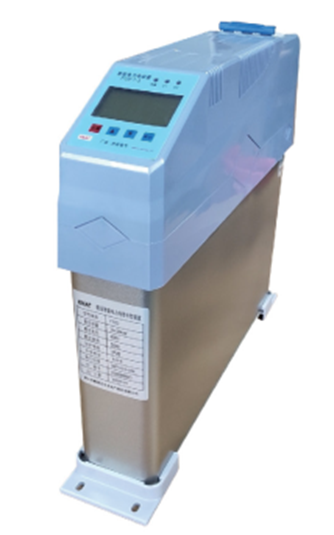
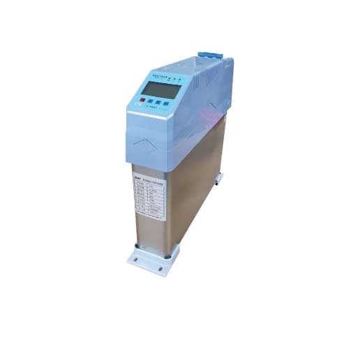
Low voltage intelligent power capacitor compensation device (FTZD type)
Low voltage intelligent power capacitor compensation device (FTZD type)
Views:
Download:
Product Introduction

I. Product overview.
The low-voltage intelligent power capacitor compensation device is a new generation of reactive power compensation equipment for 0.4KV, 50Hz low-voltage power distribution that is highly energy efficient, reduces line losses and improves power factor and power quality. It consists of an intelligent measurement and control unit, a synchronous switching circuit, a line protection unit and two low-voltage power capacitors. It replaces the conventional automatic reactive power compensation device consisting of fuses, composite switches or mechanical contactors, thermal relays, low-voltage power capacitors, indicators and other loose parts connected by wires in the cabinet and on the cabinet surface. It has changed the structure mode of traditional reactive power compensation device which is bulky and heavy, thus making the new generation of low-voltage reactive power compensation equipment with better compensation effect, smaller volume, lower power consumption, cheaper price, more cost saving, more flexible use, more convenient maintenance, longer service life and higher reliability, adapting to the higher requirements of modern power grid for reactive power compensation.
The low-voltage intelligent power capacitor compensation device adopts temperature dot matrix LCD display, which can display the three-phase bus voltage, three-phase bus voltage harmonics, frequency, capacitor road number and capacitor nominal value measured value, capacitor throwing state, capacitor current value and capacitor temperature in real time.
The low-voltage intelligent power capacitor compensation device automatically finds the best input (removal) point through the internal synchronous switching circuit to achieve arc-free switching; it guarantees over-zero switching, no inrush current, no contact sintering, micro-energy consumption, no harmonics, and at the same time has protection functions such as anti-interference and power shortage, which is especially suitable for switching capacitors during reactive power compensation without the need to install a heat sink.
II. Conditions of use.
| Elevation | ≤2000m |
| Ambient temperature | -20°C to +60°C |
| Relative humidity | 20% to 90% (at 40°C) |
| Atmospheric pressure | 79.5Kpa ~ 106KPa |
| Environmental conditions | No danger of explosion in the surrounding medium, no gas sufficient to damage insulation and corrode metal, no conductive dust, no violent vibration in the installation site, no rain or snow erosion, indoor use. |
III. Technical parameters.
3.1 Power conditions
| Operating voltage | AC380V ±20% |
| Operating frequency | 50Hz |
| Voltage waveforms | Sine wave, total distortion ≤ 5% |
| Power consumption | <0.5W (when removing capacitor), <2W (when putting in capacitor) |
3.2 Safety requirements
Meet the relevant requirements of GB/T15576-2008 "Low-voltage complete reactive power compensation device".
3.3 Measurement accuracy
| Voltage | ±0.2% |
| Current | ±0.2% |
| Active power | ±0.5% |
| Reactive power | ±0.5% |
| Frequency | ±0.2% |
| Power Factor | ±0.5% |
3.4 Protection errors
| Voltage | ≤0.5% | Current | ≤1.0% |
| Temperature | ±1°C | Time | ±0.01s |
3.5 Parameters for reactive power compensation
| Reactive power compensation error | ≤ 75% of the minimum capacitor capacity |
| Capacitor cut-off interval | >10s |
3.6 Reliability parameters
| Controlling accuracy | 100% |
| Capacitor capacity runtime decay rate | ≤1%/year |
| Capacitor capacity dropout decay rate | ≤ 0.1% / 10,000 cycles |
| Annual failure rate | 0.1% |
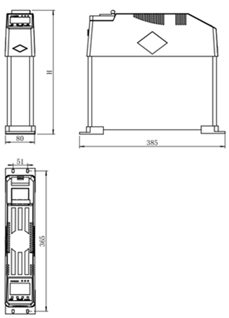
IV. Outline drawings

V. Product selection table (general parameters) Mounting hole size: 4-6*10.
| FTZD Split complement | ||||||||
| Product specifications | Throw switches |
System Voltage |
Installation Capacity |
Base wave Output capacity |
Capacitor Rated voltage |
Dimensions Length*width*height |
Mounting dimensions |
Approximate weight kg |
|
kv |
kvar |
kvar |
kv |
mm |
mm |
|||
|
FTZD-YF250(5) |
Synchronous relays |
0.22 |
5 |
4.5 |
0.25 |
385*80*250 |
365*51 |
4 |
|
FTZD-YF250(10) |
Synchronous relays |
0.22 |
10 |
9.0 |
0.25 |
385*80*250 |
365*51 |
4 |
|
FTZD-YF250(20) |
Synchronous relays |
0.22 |
20 |
18 |
0.25 |
385*80*290 |
365*51 |
5 |
|
FTZD-YF250(30) |
Synchronous relays |
0.22 |
30 |
27 |
0.25 |
385*80*330 |
365*51 |
6 |
| FTZD Co-complementary | ||||||||
|
FTZD-△F450(10+10) |
Synchronous relays |
0.4 |
20 |
15 |
0.45 |
385*80*290 |
365*51 |
5 |
|
FTZD-△F450(15+10) |
Synchronous relays |
0.4 |
25 |
19.7 |
0.45 |
385*80*290 |
365*51 |
5 |
|
FTZD-△F450(15+15) |
Synchronous relays |
0.4 |
30 |
23.7 |
0.45 |
385*80*290 |
365*51 |
5 |
|
FTZD-△F450(20+10) |
Synchronous relays |
0.4 |
30 |
23.7 |
0.45 |
385*80*330 |
365*51 |
5.5 |
|
FTZD-△F450(20+15) |
Synchronous relays |
0.4 |
35 |
27.6 |
0.45 |
385*80*330 |
365*51 |
5.5 |
|
FTZD-△F450(20+20) |
Synchronous relays |
0.4 |
40 |
31.6 |
0.45 |
385*80*330 |
365*51 |
6 |
*Due to the possibility of dimensional updates, orders are subject to the production of official drawings.
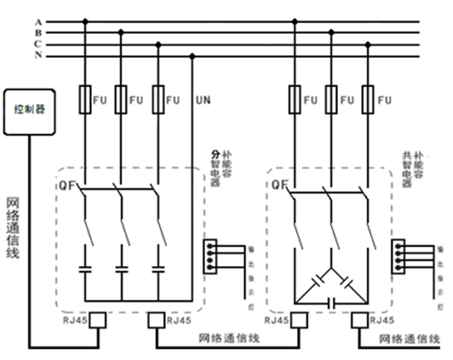
VI.intelligent power capacitor compensation device △ and Y wiring method.

VII. Notes on selection (example)

* Special specifications with different parameters can be designed to order according to customer requirements.
-
- Low voltage intelligent power capacitor compensation device (FTZD type)
Previous:
Next:
Online Consultation


