Low voltage compound switches (FTFK)
Low voltage compound switches (FTFK)
Views:
Category:
Download:
Product Introduction

Parameters
◇Ambient temperature: -25°C to +70°C
◇Altitude: no more than 2000M
◇Atmospheric conditions: air humidity not exceeding 90%
◇Environmental conditions: media free of conductive dust
How to use
◇Power indicator: When power is applied, the power indicator lights up and is in normal working condition.
◇Status indicator: always on after suction;
◇(a) When disconnected, always extinguished;
◇Fault alarm: Blinking.
Security .
◇ The installation, maintenance and operation of this compound switch is to be carried out by personnel with the relevant professional knowledge and skills.
◇ Make sure that the power supply system is a 0.4KV system and that the composite switch cannot be used for power supply systems higher than 0.4KV
◇ Ensure that the operating voltage of this compound switch (externally connected to the L terminal of the phase line and externally connected to the N terminal of the zero line) is within the range of AC220V±20% and 50HZ±10%.
◇ Do not open the housing of the composite switch at will to prevent electric shock.
Principle of operation .
The basic working principle of the FTFK series low-voltage compound switch is that the SCR is connected in parallel with a magnetic retention relay. Controlled by the internal microcontroller, the SCR undertakes over-zero throwing at the moment of input and removal, i.e. the voltage is put in at the moment of over-zero, the current is removed at the moment of over-zero, the SCR conducts for a very short time (without generating heat), after which it is converted to a magnetic holding relay to turn on and run. Therefore, it has the advantage of silicon controlled TSC switch over zero throw without inrush current, but also has the advantage of AC contactor operation without power consumption. It also avoids the defects of the SCR operating heat and contactor cutting sparks. It is a more ideal throwing switch. In particular, as the magnetically maintained relay has no inrush current or sparks at the moment of suction and disconnection, its electrical life is much higher than the designed life, while its mechanical life is up to a million times, which guarantees long-term operation.
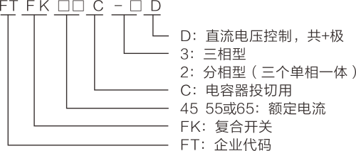
Model naming rules

Available in 4 sizes:
Three-phase: FTFK45C-3D, FTFK55C-3D ,FTFK65C-3D, FTFK85C-3D
Split phase type: FTFK45C-2D, FTFK55C-2D ,FTFK65C-2D, FTFK85C-2D
The phase-separated type is a combination of A, B and C phases, i.e. three single-phase capacitors with one compound switch. Other specifications can be produced for special orders.
Performance parameters:
| Rated voltage | AC380V+20% 50Hz± 10% |
| Rated current | 45A,55A,65A |
| Working power | AC220C± 20% 50Hz± 10% |
| Supply voltage harmonic distortion rate≦5.0% | |
| Control voltage | DC voltage 5-12V/10mA supplied by the controller |
| Power consumption of the machine |
≦3VA |
| Repeat cut time | ≦1S After removing the compound switch, it only takes 1 second to refill the capacitor without having to wait for 3 minutes for the capacitor to discharge. |
| Magnetic retention relay mechanical life |
106 times |
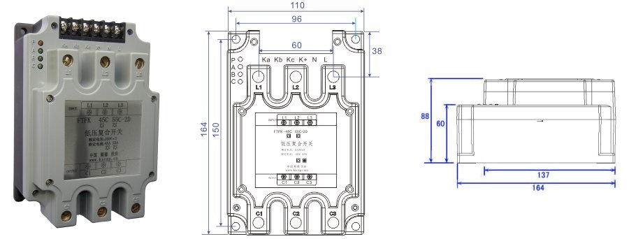
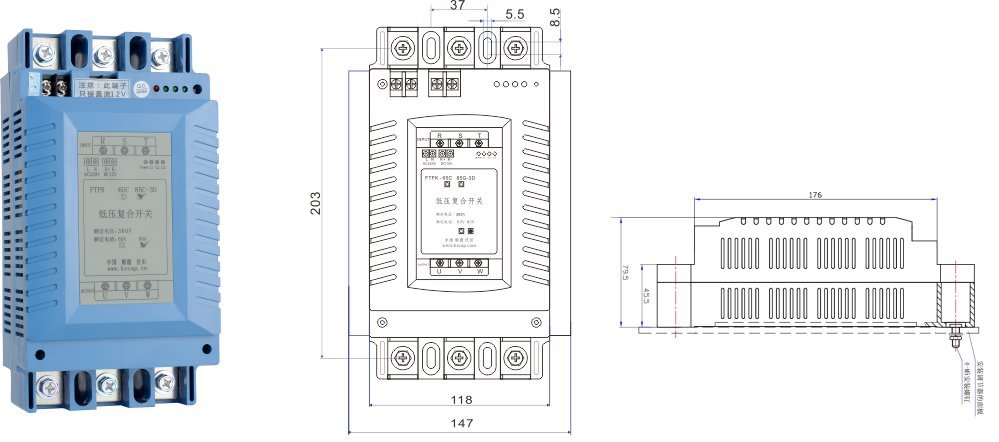
| Composite Switch External Dimensions (L*W*H) |
164*110*88(45A.55A),230*118*80MM(65A) |
| Mounting hole dimensions | 150*96mm45A.55A),(230±8),,36MM(65A) |
Selection table
| Serial number |
Type |
Model | Rated current (A) | Capacitor capacity |
|
1 |
Three-phase type |
FTTK45C-3D |
45 |
20Kvar |
|
2 |
Three-phase type |
FTTK55C-3D |
55 |
21-30Kvar |
|
3 |
Three-phase type |
FTTK65C-3D |
65 |
30-40Kvar |
|
4 |
Three-phase type |
FTTK85C-3D |
85 |
Up to 50 Kvar |
|
5 |
Three-phase type |
FTTK45C-2D |
45 |
Up to 3*606Kvar |
|
6 |
Three-phase type |
FTTK55C-2D |
55 |
3*7-3*10Kvar |
|
7 |
Three-phase type |
FTTK65C-2D |
65 |
3*10-3*15Kvar |
|
8 |
Three-phase type |
FTTK85C-2D |
85 |
up to 3*17Kvar |
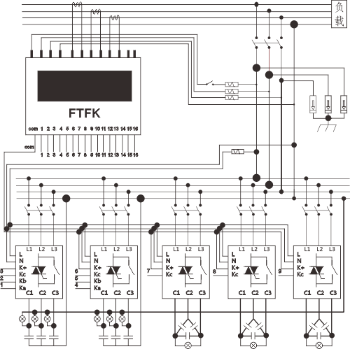
Wiring diagram

External view: ◇Size 45/55A

External view: ◇65A size

-
- Low voltage compound switches (FTFK)
Previous:
Next:
Related Products
Online Consultation


