


Product Introduction
Why reactive energy management is needed.
Principles of reactive power management.
◇In an AC circuit, the power supply provides two types of power to the load, which are active power and reactive power.
◇The active power is the electrical power that ensures the normal operation of the equipment, which is converted into other forms of energy, such as mechanical energy and internal energy.
◇The symbol for active power is P and the units are watts, kilowatts and megawatts (W, kW, MW). Reactive power is more abstract and is used for the exchange of electric and magnetic fields within a circuit, to establish and maintain magnetic fields in electrical equipment. Reactive power does not do work externally, but is simply transformed into other forms of energy. Where an electromagnetic coil is to establish a magnetic field, reactive power is consumed. The symbol for reactive power is Q, and the unit is spent, kilowatt (Var, kVar).
◇A motor needs to establish and maintain a rotating magnetic field to turn the rotor and thus drive the mechanical movement. The rotor field of a motor is established by the reactive power obtained from the power supply. The transformer also needs reactive power in order to create a magnetic field in the primary winding of the transformer and to induce an electric potential in the secondary winding. Without reactive power the motor will not turn and the transformer will not change voltage.
◇Under normal circumstances, the electrical load not only needs to obtain power from the power supply, but also needs to obtain reactive power. If the reactive power supply in the grid is insufficient, the power-using equipment will not have enough reactive power to build up the electromagnetic field, and the equipment will not be able to work in its rated condition, and the voltage at the end of the equipment will drop and affect normal operation.
◇The traditional correction solution is to connect capacitors, which compensate for the reactive energy consumed by the load. Due to technological advances, it is now also possible to use static reactive generators (SVG) to generate capacitive or inductive currents to compensate for the reactive energy required by the load. The direct result of this use is an increase in power factor, a reduction in apparent power and a reduction in power losses in the transmission network, resulting in a higher transmission capacity.
Benefits from reactive power management
◇The transmission of reactive power in the grid is of great technical and economic importance. In a circuit, in addition to active energy, reactive energy also needs to be provided. Higher reactive power means higher apparent power and current for the same amount of active power, so generating reactive energy close to the load to avoid unnecessary current transmission is known as "power factor correction".

Taken together, reactive power management brings the following benefits:
◇Avoidance of reactive power losses, resulting in lower apparent power
◇Reduced line and transformer losses
◇Increase in available power
◇Reduced cross-sectional area of conductors
◇Reducing the voltage drop of equipment and avoiding overloads

Reduces the output power of the motor, which affects its long-term reliable operation;
◇Reduces the output power of the motor and raises the temperature of its windings, which may jeopardize its safe operation;
◇It may further cause the three-phase voltage to be unbalanced, resulting in the power-using equipment mounted on the high-voltage phase burning out, while the power-using equipment mounted on the low-voltage phase cannot be used normally.
Conventional three-phase unbalance regulation and its characteristics:
Installation of electronic phase change switch:
◇According to the three-phase imbalance of the system, the single-phase load is switched to the appropriate phase by means of an electronic switch. It is necessary to divide all single-phase or two-phase loads into several groups according to the three phases of ABC, and each group is controlled by an electronic switch for phase change. To a certain extent, this alleviates the three-phase imbalance, but when the load changes dynamically within each group or the grouping is not precise enough, the system will always have a three-phase imbalance. In addition, there are voltage flickers and dips during the phase change process.
Throwing and cutting inter-phase and phase-splitting capacitors:
◇According to wangs theorem (Wang's theorem), bidding and cutting the split-phase capacitors regulates the reactive current in each phase, and bidding and cutting the inter-phase capacitors transfers the active current between phases. The specific regulation effect of the three-phase imbalance depends on the number of groupings and the capacity grade difference between the inter-phase capacitors and the phase-splitting capacitors. In practice, the system is still unbalanced to a certain extent due to the discrete capacity of the capacitors, and the frequent round tripping of the capacitors accelerates their ageing when the load changes rapidly. In addition, in some applications it is not possible to combine reactive power compensation and three-phase unbalanced current regulation at the same time.
Use of static reactive power compensation devices:
◇The most commonly used static reactive power compensation device (SVC) is generally a fixed capacitor (FC) + a thyristor-controlled reactor (TCR). According to the Steinmetz theory and the instantaneous reactive power algorithm, the three-phase compensation conductance of the system is calculated, the trigger angle of each phase of the TCR is controlled and the reactive power of the split phase and the inter-phase is adjusted:
◇In order to determine the required amount of reactive power compensation, mathematical calculation methods are used.
◇Qc=P×(tanφ-tanφ') can be obtained from vector diagram analysis and trigonometric functions, where φ is the power factor angle and cosφ is the power factor (PowerFactor). When the load power P, the original power factor cosφ and the target power factor cosφ' are known, the value of the reactive power to be compensated can be calculated.
Determination of reactive power compensation methods:
◇Centralized compensation: Compensation devices are placed on the busbar to compensate for all loads;
◇Group compensation: Compensation devices are placed under the main switch of the department to compensate for some loads;
◇Local compensation: Compensation devices are placed under the end switches of power-using equipment for targeted compensation.
◇Local compensation: Compensation devices are placed under the end switches of power-using equipment to provide targeted compensation.
Determination of the reactive power compensation control mode:
◇Fixed compensation: the amount of reactive power to be compensated is a fixed value, for a relatively smooth reactive power demand;
◇Automatic compensation: The compensation elements are capacitors grouped according to capacity or continuously adjustable SVG devices, which determine the amount of compensation in response to the dynamically changing reactive power demand of the load (power factor criterion).
The importance of three-phase unbalance regulation.
The dangers of three-phase imbalance.
◇ In the low-voltage distribution network system, the three-phase four-wire system is generally adopted, and the power terminals are mostly used for single-phase loads or single-phase and three-phase loads, and the load sizes are different and the power consumption time is not fixed. Three phase current imbalance is widely present in the network and the imbalance has irregularity, which has the following main hazards for power distribution and power-using equipment:
◇Additional power loss in the lines, resulting in unnecessary electricity expenses for users;
◇Increases the copper loss of the distribution transformer, minus, realizes the smooth regulation of the three-phase unbalanced current. In actual use, the TCR itself will generate some low harmonic currents, and when the filtering parameters of the FC are not properly designed, it will also cause harmonic amplification.
The importance of three-phase unbalance regulation.
Principle of operation.
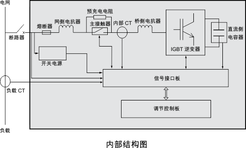
◇The main circuit topology is similar to that of an active filter, and the parameters of the grid-connected components have been optimised to make it more suitable for unbalanced control of the system's fundamental current. It collects the three-phase current waveform of the system in real time and extracts the positive sequence, negative sequence and zero sequence waveforms of the fundamental waveform current, integrates the reactive power compensation and three-phase unbalance requirements of the system, and instantly synthesises the corresponding command waveform to the IGBT inverter to output a current that can offset the three-phase unbalance of the system.
Job Benefits:
◇Smooth adjustment of three-phase imbalance can be achieved;
◇Both reactive power compensation and three-phase unbalance adjustment can be achieved;
◇Fast response speed, no voltage flicker and fluctuation;
◇No harmonic current pollution.

Current waveform under conventional compensation

Voltage waveform under conventional compensation

Current under the action of a three-phase unbalance regulator

Voltage under the action of a three-phase unbalance regulator
The need for harmonic control.
Harmonic pollution of the electricity network.
What are harmonics? What are interharmonics?
◇Harmonics are electrical quantities contained in voltages or currents with frequencies that are integer multiples of the fundamental wave, generally those generated by Fourier series decomposition of periodic non-sinusoidal electrical quantities and the remaining currents that are greater than the fundamental wave frequency. Then non-integer multiples of the voltage and current we call interharmonics, whose frequency is between the harmonics, e.g. 130 Hz (between the 2nd 100 Hz and the 3rd 150 Hz).
What are the causes of harmonics?
◇Harmonics are generated by the distortion of the fundamental wave current due to the sinusoidal voltage applied to a non-linear load. The main non-linear loads are UPS, switching power supplies, rectifiers, inverters, inverters, lifts, air conditioners, energy-saving lighting, etc.
Harmonic hazards
◇ A large number of 3rd harmonics will lead to overcurrent, overheating and even fire in the neutral line;
◇Reducing the effective carrying capacity of power distribution equipment (e.g. transformers, cables);
◇Overheating of cables and deterioration of insulation. The higher the number of harmonics, the higher the harmonic heat loss (I2Rt); the heat generated by the 5th harmonic current of 10A is 5 times that of the fundamental current of 10A;
◇ Causing circuit breaker malfunction and causing errors in measuring equipment;
◇Interference with communication and micro-electronic equipment;
◇ Causes over-current and over-voltage in power factor compensation capacitors and accelerates the ageing of components;
◇Skin collecting effect;
◇Resonance in the power grid;
◇ Interharmonics can cause generator shafts to break due to pressure.
Principle of active filter function
◇APF and SVG devices collect current signals in real time through external current transformers, separate the harmonic components in them through internal detection circuits, and invert compensation currents of equal size and opposite phase to the harmonics in the system through IGBTs to realise the function of filtering harmonics (closed-loop control).
◇Active filtering is a filtering device for dynamic suppression of harmonics, which can track the harmonic components to be compensated very well and does not need to be designed to compensate for a specific number of harmonics, and has universal application.
Compared to conventional LC passive filters, APFs have the following distinct advantages:
◇ Dynamic, real-time compensation with good filtering effect;
◇The APF controls its own output according to the change of harmonic frequency, without having to be designed according to a specific load, and the APF does not easily resonate in series with the grid impedance;
◇The rated capacity of the original components in an APF is much smaller than that of the inductor-capacitor in an LC circuit. The APF will not overload the output during the compensation process;
◇In addition to filtering out most harmonics, APF devices can also compensate reactive currents, thus achieving full compensation;
◇ Compared to LC circuits with triangular connections, APF units with split phase detection and output are more suitable for harmonic and reactive power imbalance applications.
Direct benefits from optimising power quality
After reducing harmonic currents, compensating for reactive power and three-phase imbalances, the following benefits can be obtained
The following benefits are achieved:
◇Minimizing the impact of harmonics on other loads and optimizing equipment working conditions;
◇Reducing cable losses and heat generation, and improving the reliability of power supply;
◇Reducing transformer losses, increasing the effective capacity of the transformer, increasing the corresponding carrying capacity and reducing the investment required for capacity expansion;
◇Improves the safe operation coefficient of the transformer and serves the purpose of energy saving and consumption reduction.
Methods for determining harmonic compensation requirements
◇ The selection of the harmonic current compensation capacity involves a number of factors and requires field measurements or preliminary design estimates; accurate predictions require simulation modelling, and the process is very complex. The design process for optimisation and renovation projects uses the following method to obtain the values of each harmonic current component of the load, and then determines the capacity size of the active filter based on the specifics of the harmonic current. The table below shows the harmonic current of a particular load, which is calculated to have an RMS value of approximately 60A.

New construction projects, where harmonics cannot be accurately measured, can be estimated by
the following equation to estimate:
IH = 0.15 x K1 x K2 x St
Where: IH - bus-side harmonic current
St - transformer capacity
K1 - transformer load factor (can be 75%)
K2 - compensation coefficient
For general office buildings and commercial buildings, K2 can be taken as 0.3 to 0.6;
For computers, energy-saving lamps, inverter equipment relatively concentrated office buildings, stadiums, theatres, media buildings, general factories can take 0.6 ~ 1.3; data centres, communication base stations, electric arc furnaces, large-scale UPS/EPS, inverters, welding, electroplating, electrolysis, rectification and other factories can take 1.3 ~ 1.8.
Application areas and characteristics.
◇The flexible and powerful industrial APF series is a powerful industrial PQM in a standard 19" form factor, with high system availability to meet the needs of high performance applications.
Suitable for horizontal and vertical installation, they are suitable for use in a variety of environments and facilitate the completion of various correction tasks.
◇Intuitive comparative analysis of electrical energy data
◇Good dynamic adjustment of three-phase current imbalance
◇Real-time dynamic reactive power compensation adjustment
◇Industrial-grade product performance and superb wave filtering compensation capability
◇Intelligent power quality management
Product Principle
◇APF series products collect the load current signal in real time through the external transformer CT, separate the reactive power and harmonic current size through the internal detection circuit, and adaptively output the ZVPWM signal to the IGBT, through which the IGBT inverts the current of the same size and phase opposite to the load to achieve dynamic reactive power compensation and harmonic filtering in real time. The output current of the APF series is dynamically changed according to the system reactive power demand and the amount of harmonics, so there is no over-compensation and the flexible reactive power compensation does not produce inrush shocks.

| Model number | APF |
| Performance voltage | |
| Operating voltage | 220V/400V/690V/1100V (±20%) |
| Operating frequency | 50Hz/60Hz (±10%) |
| Power rating | 25A/30A/35A/50A/60A/75A/80A/100A/120A (larger capacities can be extended by parallel connection and coordinated by a unified control unit) |
| Filter function | - |
| Filter range | 2-50 times |
| Overall machine efficiency | ≧98% |
| Filtering skills | < 5% THDI (rated capacity) |
| Compensation function | - |
| Range of reactive power compensation | -0.98~+1 (adjustable) |
| Reactive power compensation capacity | >99% (rated capacity) |
| Unbalance function | - |
| Unbalance adjustment range | Split-phase power factor 0.95 to 1 (within capacity range) |
| Imbalance adjustment capacity | Unbalance ≦3% (within capacity) |
| Response time | < 1ms |
| Full response time | < 10ms |
| Switching frequency | 20kHz |
| Overload protection | - |
| Display operations | |
| 5" touch screen | - |
| 8" touch screen | ◎ |
| Show content | Current parameters/expert parameters/main wiring diagrams/event logs/wave curves etc. |
| Display language | Chinese/English etc. |
| Mode of operation | Panel touch/automatic hand switch |
| Communication methods | |
| Hardware interfaces | RS485/Ethenet |
| Communication protocols | Modbus, CDT |
| Environmental conditions | |
| Ambient temperature | -25°C~45°C |
| Storage temperature | -40°C-70°C |
| Relative temperature | 95% max, no condensation |
| Elevation | Below 1500m |
| Note: ◎ means this function is available, - means it is optional, for more specifications please contact Fuda | |
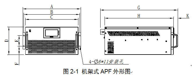

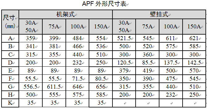
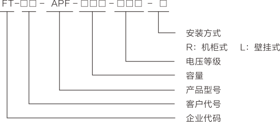
Model naming rules
Installation wiring

Application options
Compensation methods
1. Integrated compensation
Integrated compensation is suitable for mixed distribution systems, where the number of non-linear loads is large and dispersed, and the harmonic content of individual non-linear loads is small. Voltaic Kscap active power filters can be installed at the access end of the grid to provide integrated management of all harmonics in the distribution system.

2. Partial compensation
Partial compensation is suitable for distribution systems where non-linear loads are concentrated in a few branches. Voltaic Kscap active power filters can be installed at the upper end of these branches to ensure that harmonics do not flow into the grid and pollute other loads.

3. Local compensation
Local compensation is suitable for distribution systems with concentrated non-linear loads and a large harmonic content in a single unit, where the ideal effect can be achieved by installing a Voda Kscap active power filter at the front end of the load.

-
- Active filters (FT-APF)
Previous:
Next:
Related Products
")
Online Consultation
Our products are widely used in fields such as reactive power compensation and filtering systems, power electronics, new energy, and household appliances.
CONTACT
Add: No. 36 Xingmin Road, Hecheng Street, Gaoming District, Foshan City
Tel: 0757-27886317/ 0757-27330976
Fax: 0757-27330975
Web: www.kscap.cn
E-mail: sale@kscap.cn

OFFICIAL ACCOUNT