

.jpg")
Low-voltage intelligent harmonic suppression power capacitor compensation device (thyristor)
Low-voltage intelligent harmonic suppression power capacitor compensation device (thyristor)
Views:
Category:
Download:
Product Introduction
I. Product overview
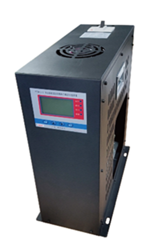
This low-voltage intelligent harmonic suppression power capacitor compensation device is a new generation of 0.4KV, 50Hz low-voltage power distribution high-efficiency energy saving, line loss reduction, power factor improvement and power quality harmonic reactive power compensation equipment. It consists of an intelligent measurement and control unit, a line protection unit, a (△ type) or a (Y type) low-voltage power capacitor and reactor. It replaces the conventional automatic reactive harmonic suppression compensation device composed of fuses, composite switches or mechanical contactors, thermal relays, low-voltage power capacitors, indicators and other loose parts connected by wires in the cabinet and on the cabinet surface. It has changed the structure mode of traditional reactive power compensation device which is bulky and heavy, thus making a new generation of low-voltage reactive power compensation equipment with better compensation effect, smaller volume, lower power consumption, cheaper price, more cost saving, more flexible use, more convenient maintenance, longer service life and higher reliability, adapting to the higher requirements of modern power grid for reactive power compensation.
The low-voltage intelligent harmonic suppression power capacitor compensation device adopts a customised segment LCD display, which can display the busbar voltage, the total harmonic content of the voltage, the temperature of the capacitor, the reactive power and the capacitor's throwing status in real time.
The low-voltage intelligent harmonic suppression power capacitor compensation device automatically searches for the best input (removal) point through the internal thyristor switching circuit to achieve arc-free switching; it ensures over-zero switching, no inrush current, no contact sintering, micro energy consumption, no harmonics, and at the same time has protection functions such as anti-interference and power shortage, especially suitable for switching capacitors during reactive power compensation, in addition, the thyristor is also configured with a heat sink, so that the performance is more In addition, the thyristor is also equipped with a heat sink, so that the performance is more stable and the life span is further extended.
II. Conditions of use.
| Elevation | ≤2000m |
| Ambient temperature | -25 to 55°C |
| Relative humidity | 40°C, 20 to 90% |
| Atmospheric pressure | 79.5 to 106.0 Kpa |
| Environmental conditions | No conductive dust and corrosive gases in the surrounding badlands, no flammable and explosive media, indoor type. |
III. Technical parameters.
3.1 Power conditions.
| Rated voltage | AC 380V |
| Allowable Deviation | ±20% |
| Voltage waveforms | Sine wave with a total distortion of not more than 5% |
| Industrial frequency | 48.5 to 51.5 Hz |
| Power consumption | <0.5W (when removing capacitors), <1W (when putting in capacitors) |
3.2 Safety requirements.
Meet the relevant requirements of GB/T15576-2008 "Low-voltage complete reactive power compensation device".
3.3 Measurement errors.
| Voltage | ±0.2% |
| Current | ±0.2% |
| Active power | ±0.5% |
| Reactive power | ±0.5% |
| Frequency | ±0.2% |
| Power Factor | ±0.5% |
3.4 Protection errors.
| Voltage | ≤0.5% |
| Current | ≤1.0% |
| Temperature | ±1°C |
| Time | ±0.01s |
3.5 Parameters for reactive power compensation.
| Reactive power compensation error | ≤ 75% of the minimum capacity |
| Capacitor cut-off interval | >10s |
| Reactive capacity | Single unit ≤ 40kvar |
3.6 Reliability parameters.
| Controlling accuracy | 100% |
| Capacitor capacity runtime decay rate | ≤1%/year |
| Capacitor capacity dropout decay rate | ≤ 0.1% / 10,000 cycles |
| Annual failure rate | 0.1% |
*Please specify any other special requirements and performance parameters when ordering.
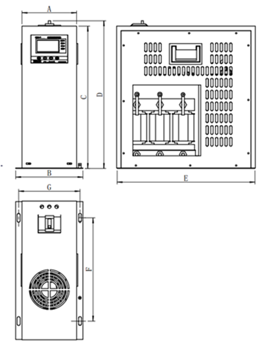
3.7 Outline drawing of thyristor-throwing switch
3.8 Thyristor product selection table (general parameters)
| FTZM-L Vertical splitting type | |||||||||||||
| Product specifications |
Toggle Switch |
System Voltage |
Installation Capacity |
Base-wave output capacity |
Capacitor Rated voltage |
Approximate weight kg |
External dimensions (mm) | ||||||
|
kv |
kvar |
kvar |
kv |
A |
B |
C |
D |
E |
F |
G |
|||
|
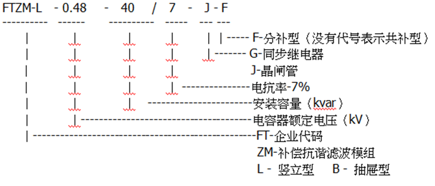
FTZM-L-0.28-10/7-J-F |
Thyristor |
0.22 |
10 |
6.64 |
0.28 |
28 |
185 |
228 |
480 |
510 |
470 |
345 |
208 |
|
FTZM-L-0.28-20/7-J-F |
Thyristor |
0.22 |
20 |
13.3 |
0.28 |
30 |
|||||||
|
FTZM-L-0.28-30/7-J-F |
Thyristor |
0.22 |
30 |
19.91 |
0.28 |
33 |
|||||||
| FTZM-L Vertical type (co-patch type) | |||||||||||||
|
FTZM-L-0.48-20/7-J |
Thyristor |
0.4 |
20 |
14.5 |
0.48 |
29 |
185 |
228 |
480 |
510 |
470 |
345 |
208 |
|
FTZM-L-0.48-30/7-J |
Thyristor |
0.4 |
30 |
22.4 |
0.48 |
31 |
|||||||
|
FTZM-L-0.48-33.5/7-J |
Thyristor |
0.4 |
33.5 |
25 |
0.48 |
35 |
|||||||
|
FTZM-L-0.48-40/7-J |
Thyristor |
0.4 |
40 |
30 |
0.48 |
38 |
|||||||
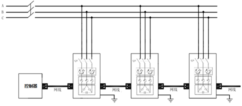
3.9 Low-voltage intelligent harmonic suppression power capacitor compensation device wiring schematic (common complementary diagram)
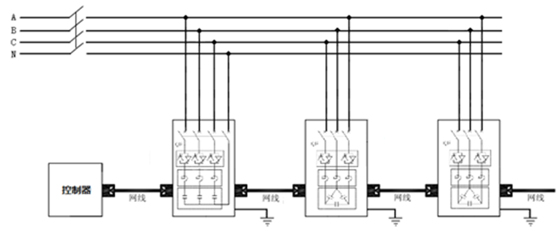
3.10 Low-voltage intelligent harmonic suppression power capacitor compensation device wiring schematic (sub-complementary diagram)
IV. Notes on selection:
* Special specifications with different parameters can be designed to order according to customer requirements.
-
- Low-voltage intelligent harmonic suppression power capacitor compensation device (thyristor)
Previous:
Next:
Related Products
")
Online Consultation
Our products are widely used in fields such as reactive power compensation and filtering systems, power electronics, new energy, and household appliances.
CONTACT
Add: No. 36 Xingmin Road, Hecheng Street, Gaoming District, Foshan City
Tel: 0757-27886317/ 0757-27330976
Fax: 0757-27330975
Web: www.kscap.cn
E-mail: sale@kscap.cn

OFFICIAL ACCOUNT