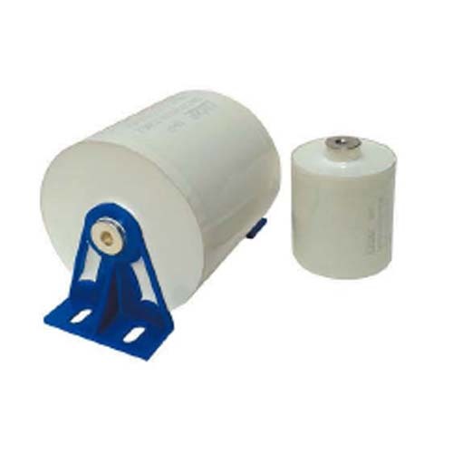
PE tape high frequency resonance type capacitors (MKP-GW series)
PE tape high frequency resonance type capacitors (MKP-GW series)
Views:
Category:
Download:
Product Introduction

Product features
■ Double-sided vapour plating structure, able to withstand high voltages and high over-current capability
■ Low self-inductance, low temperature rise
■ Dry construction, solid epoxy encapsulation
■ Electronic insulating tape wrapping (optional mounting bracket for simplicity and convenience)
■ Low equivalent series resistance
Note .
Please contact us for other electrical capacities, dimensions and performance parameters.
Typical applications
■ Widely used in series and parallel circuits for medium and high frequencies, e.g. in resonant circuits such as welding machines, induction heating, etc. Also used in other power electronics.
Performance parameters
| Reference Standards |
IEC61071 GB17702 IEC60110 GB/T3984 |
| Rated voltage |
1000VDC~3000VDC (500VAC~1000VAC) |
| Rated capacity (general purpose specification) |
0.33uF~10uF 1KHz @ +25℃ |
| Electrical capacity deviation |
±5 %(J) ±10 %(K)Other deviations optional @ 100Hz @+25℃ |
| Operating temperature range |
-40℃ ~+85℃ |
| Storage temperature range |
-40℃ ~+85℃ |
|
Attrition factors (DF) |
tgδ≤0.0006 @ 1KHz @ +25℃ |
|
Insulation resistance(IR) |
Typical values(Ris x C): ≥5000S Temperature.: +25 °C @ 1min & Test voltage: 100 Vdc |
|
Dielectric strength(Ut-t) |
1.5UnContinuous 10S |
|
Electrode to shell voltage strength(Ut-c) |
3000VAC 2 seconds @+25℃ 50/60Hz |
| Life expectancy |
100,000hours at Un and Th≤ 70°C |
|
Dielectric materials |
Metallised double-sided vapour plated inner string construction |
| Electrode lead-out |
Brass nuts(M6/M8)(M6≤4N.m,M8≤6N.m/Refer toIEC61881) |
| Outer protective surface / housing |
Wrapped in white electrical insulation tape (optional with mounting bracket) |
| Internal filler |
Insulation fillers(UL94- V0) |
|
Note: If the altitude of use exceeds 2000m, the effects of convection cooling and external insulation should be considered. |
|
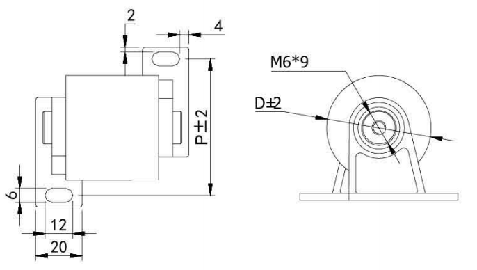
Outline drawing


General parameters:
|
MKP-GW Un=1000VDC Urms=500VAC Cn= 1.5~10.0μF |
||||||||
|
Catalog Part Number |
C |
D |
H |
ESR @25℃ 10KHz |
ESL @25℃ 10KHz |
dv/dt |
Ipk |
Irms @40℃ 100KHz |
|
μF |
mm |
mm |
mΩ |
nH |
V/us |
A |
A |
|
|
MKP-GW155J1000VL40M6 |
1.5 |
38 |
40 |
5.1 |
27 |
1000 |
1500 |
22 |
|
MKP-GW205J1000VL40M6 |
2.0 |
44 |
40 |
4.7 |
30 |
1000 |
2000 |
31 |
|
MKP-GW305J1000VL40M6 |
3.0 |
54 |
40 |
4.3 |
38 |
1000 |
3000 |
42 |
|
MKP-GW405J1000VL40M6 |
4.0 |
62 |
40 |
3.9 |
43 |
900 |
3600 |
50 |
|
MKP-GW505J1000VL40M6 |
5.0 |
69 |
40 |
3.6 |
47 |
900 |
4500 |
58 |
|
MKP-GW605J1000VL40M6 |
6.0 |
75 |
40 |
3.4 |
52 |
900 |
5400 |
63 |
|
MKP-GW805J1000VL50M6 |
8.0 |
69 |
50 |
3.1 |
61 |
800 |
6400 |
55 |
|
MKP-GW106J1000VL50M6 |
10.0 |
76 |
50 |
2.9 |
68 |
800 |
8000 |
60 |
|
MKP-GW Un=1200VDC Urms=550VAC Cn= 1.0~8.0μF |
||||||||
|
Catalog Part Number |
C |
D |
H |
ESR @25℃ 10KHz |
ESL @25℃ 10KHz |
dv/dt |
Ipk |
Irms @40℃ 100KHz |
|
μF |
mm |
mm |
mΩ |
nH |
V/us |
A |
A |
|
|
MKP-GW105J1200VL40M6 |
1.0 |
36 |
40 |
5.6 |
25 |
1100 |
1100 |
26 |
|
MKP-GW205J1200VL40M6 |
2.0 |
49 |
40 |
5.2 |
32 |
1000 |
2200 |
35 |
|
MKP-GW405J1200VL40M6 |
4.0 |
60 |
40 |
4.3 |
39 |
1000 |
4000 |
50 |
|
MKP-GW505J1200VL50M6 |
5.0 |
55 |
50 |
4.0 |
45 |
900 |
4500 |
45 |
|
MKP-GW605J1200VL50M6 |
6.0 |
60 |
50 |
3.6 |
50 |
900 |
5400 |
50 |
|
MKP-GW805J1200VL50M6 |
8.0 |
68 |
50 |
3.1 |
57 |
900 |
7200 |
58 |
|
MKP-GW Un=1600VDC Urms=600VAC Cn= 0.68~5.0μF |
||||||||
|
Catalog Part Number |
C |
D |
H |
ESR @25℃ 10KHz |
ESL @25℃ 10KHz |
dv/dt |
Ipk |
Irms @40℃ 100KHz |
|
μF |
mm |
mm |
mΩ |
nH |
V/us |
A |
A |
|
|
MKP-GW684J1600VL40M6 |
0.68 |
36 |
40 |
5.9 |
22 |
1100 |
748 |
25 |
|
MKP-GW105J1600VL40M6 |
1.0 |
43 |
40 |
5.6 |
26 |
1100 |
1100 |
30 |
|
MKP-GW205J1600VL40M6 |
2.0 |
50 |
40 |
5.2 |
32 |
1100 |
2200 |
38 |
|
MKP-GW305J1600VL40M6 |
3.0 |
60 |
40 |
4.5 |
38 |
1100 |
3300 |
43 |
|
MKP-GW405J1600VL50M6 |
4.0 |
57 |
50 |
4.1 |
43 |
900 |
3600 |
40 |
|
MKP-GW505J1600VL50M6 |
5.0 |
64 |
50 |
3.5 |
49 |
900 |
4500 |
50 |
|
MKP-GW Un=2000VDC Urms=750VAC Cn= 0.47~4.0μF |
||||||||
|
Catalog Part Number |
C |
D |
H |
ESR @25℃ 10KHz |
ESL @25℃ 10KHz |
dv/dt |
Ipk |
Irms @40℃ 100KHz |
|
μF |
mm |
mm |
mΩ |
nH |
V/us |
A |
A |
|
|
MKP-GW474J2000VL40M6 |
0.47 |
36 |
40 |
6.2 |
21 |
1200 |
564 |
23 |
|
MKP-GW105J2000VL40M6 |
1.0 |
50 |
40 |
5.7 |
29 |
1200 |
1200 |
36 |
|
MKP-GW205J2000VL50M6 |
2.0 |
55 |
50 |
5.1 |
38 |
1000 |
2000 |
48 |
|
MKP-GW305J2000VL50M6 |
3.0 |
67 |
50 |
4.6 |
46 |
1000 |
3000 |
58 |
|
MKP-GW405J2000VL50M6 |
4.0 |
70 |
50 |
4.1 |
50 |
900 |
3600 |
58 |
|
MKP-GW Un=3000VDC Urms=1000VAC Cn= 0.33~2.0μF |
||||||||
|
Catalog Part Number |
C |
D |
H |
ESR @25℃ 10KHz |
ESL @25℃ 10KHz |
dv/dt |
Ipk |
Irms @40℃ 100KHz |
|
μF |
mm |
mm |
mΩ |
nH |
V/us |
A |
A |
|
|
MKP-GW334J3000VL40M6 |
0.33 |
36 |
40 |
6.4 |
19 |
1250 |
412.5 |
23 |
|
MKP-GW474J3000VL40M6 |
0.47 |
42 |
40 |
5.7 |
25 |
1250 |
587.5 |
30 |
|
MKP-GW684J3000VL40M6 |
0.68 |
51 |
40 |
5.2 |
28 |
1250 |
850 |
35 |
|
MKP-GW804J3000VL40M6 |
0.80 |
55 |
40 |
4.6 |
37 |
1250 |
1000 |
43 |
|
MKP-GW105J3000VL40M6 |
1.00 |
61 |
40 |
4.2 |
40 |
1250 |
1250 |
50 |
|
MKP-GW205J3000VL50M6 |
2.00 |
70 |
50 |
4.0 |
48 |
1250 |
1250 |
56 |
Selection notes:
MKP-GW 105 J 1200V L40 M6
------ --- --- --- ----- ---
∣ ∣ ∣ ∣ ∣ ∣------------- indicates lead-in M6 nut
∣ ∣ ∣ ∣ ∣ -------------------Capacitor length: L=40mm
∣ ∣ ∣ ∣ --------------------------Rated voltage: Un=1200VDC
∣ ∣ ∣ -------------------------------Capacitance tolerance: J(±5%), K(±10%)
∣ ∣-------------------------------------Rated capacity: Cn=1.0 uF
∣--------------------------------------------High frequency resonant capacitors (GW for type)
Different parameters can be designed according to customer requirements. For more choices of AC and DC filter capacitor types, please refer to other specifications of metalised film capacitors.
-
- PE tape high frequency resonance type capacitors (MKP-GW series)
Next:
Related Products
Online Consultation


