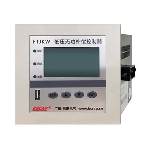
Low-voltage reactive power compensation controller (for intelligent capacitors) (FTJKW-64F-U-X)
Low-voltage reactive power compensation controller (for intelligent capacitors) (FTJKW-64F-U-X)
Views:
Download:
Product Introduction
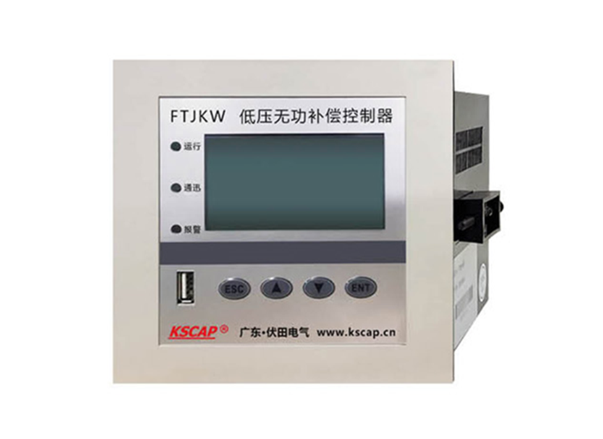
I. Product overview.
This product conforms to the JB/T9663-2013 and DL/T597-1996 standards. It is a special controller for reactive power compensation in low-voltage distribution systems and can be used with various types of low-voltage distribution capacitors. The product adopts advanced technology at home and abroad and has the advantages of reasonable and beautiful appearance, perfect function, stable and reliable operation and high compensation accuracy.
II. Product selection.
| FTJKW-64F-U-X | Mix-and-match intelligent controller (temperature-controlled) |
III. Product shape and installation dimensions.
| Dimensions | 143mm x 143mm |
| Mounting cut-out dimensions | 138mm x 138mm |
| Thickness | 95mm |
IV. Conditions of use
| Elevation | ≤2000m |
| Ambient temperature | -20°C to +60°C |
| Relative humidity | 20% to 90% (at 40°C) |
| Atmospheric pressure | 79.5Kpa ~ 106KPa |
| Environmental conditions | No danger of explosion in the surrounding medium, no gas sufficient to damage insulation and corrode metal, no conductive dust, no violent vibration in the installation site, no rain or snow erosion, indoor type. |
V. Technical parameters
5.1 Basic parameters
| Supply voltage | AC 220V±20% |
| Power supply frequency | 50Hz±5% |
| Sampling voltage | AC 220V±20% |
| Sampling current | 0 to 6A |
| Power consumption of the whole machine | 6W |
| Control output contact | RJ45 |
| Sensitivity | 20mA |
5.2 Measurement accuracy
| Voltage | ±0.5% |
| Current | ±0.5% |
| Active power | ±1.0% |
| Reactive power | ±1.0% |
| Frequency | ±0.1% |
| Power Factor | ±1.0% |
5.3 Control parameters.
| Parameters | Parameter range | Default value |
| Current ratio | 0000/5 to 9999/5 | 0600/5 |
| Voltage ratio | 0000V to 9999V | 0400/400 |
| Voltage overvoltage | 000V to 999V | 245V |
| Voltage undervoltage | 000V to 999V | 185V |
| Voltage Return | 0.0V to 9.9V | 5.5V |
| Voltage harmonic protection | 00% to 99% |
10% |
| Current harmonic protection | 00% to 99% | 30% |
| Vote power factor | Lagging 0.00 to 1.00 | Lagging 0.95 |
| Cut Power Factor | Over/under 0.00 to 1.00 | 0.98 ahead of schedule |
| Put in waiting time delay | 00s to 99s |
05s |
| Cut off waiting delay | 00s to 99s | 05s |
| Switch response wait | 00.0s to 25.5s | 00.1s |
| Cycle cut interval | 0000s to 9999s | 3600s |
| Capacitor discharge time | 000s to 255s |
030s |
| Duration of protection | 000s to 255s | 030s |
| Manual duration | 0000 to 9999 | 0060s |
| Fan start-up temperature | 00 to 99 | 40°C |
| Alarm temperature | 00 to 99 | 60°C |
| Correspondence address | 000 to 255 | 001 |
| Password setting | 0000 to 9999 | 0000 |
VI. Control wiring schematic.
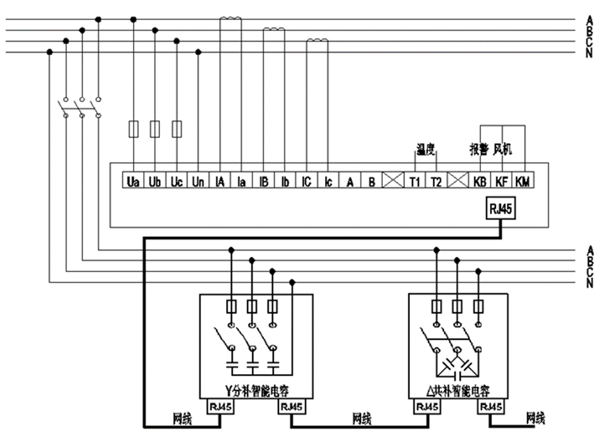
VII. Description of terminal definitions.
| Terminal number | Status | Details |
| Ua, Ub, Uc, Un. | Voltage input | Connection of three-phase voltage and zero line |
| IA, Ia; IB, Ib; IC, Ic | Current input | Connecting three-phase current transformers |
| A, B | RS485 output | Optional, protocol adaptation required |
| T1, T2 | Temperature input | Connected to PT100 |
| KM, KF, KB | Dry contact output | KM to common, to phase, KF to fan, KB to alarm |
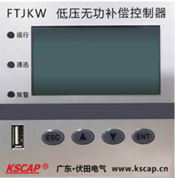
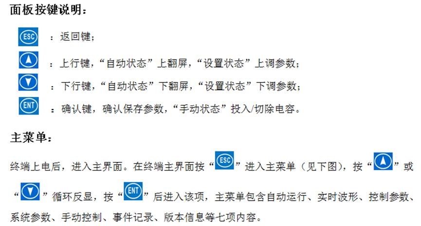
VIII. Operating instructions.
-
- Low-voltage reactive power compensation controller
Previous:
Next:
Related Products
Online Consultation


