


Filter assemblies (capacitors + reactors) (FTCE series)
Filter assemblies (capacitors + reactors) (FTCE series)
Views:
Category:
Download:
Product Introduction

Selection of reactors:
I. For new design projects:
◇Reactance 7% (or 5.67%) - for industrial projects (5th harmonic or higher)
◇Reactance 14% - for residential building projects (3rd harmonic or higher)
II. For renovation projects:
◇If the harmonic content of the system is detected and THDI > 10%orTHD - V > 3%, a standard detuning filter can be used to solve the problem.
◇If the content of the 3rd harmonic current is greater than 20% of the 5th harmonic current, a detuning filter with p = 14% should be used.
◇If the system is mainly 5th harmonic and the 3rd harmonic is relatively small, a detuning filter with p = 7% can be used.
◇Detect the total harmonic distortion rate THD - V of the voltage of the system, e.g. THD - V = 3% to 7%, using a de-rating of p = 7% harmonic filter.
◇If THD - V > 7%, a detuning filter with p = 5.67% can be used, if THD - V > 10%, a special detuning filter is required.
◇In addition, for systems with a current harmonic distortion rate THD - 1 greater than 20%, a detuned filter with p = 5.67% is preferable.
Capacitor selection:
I. Selection of capacitor voltage levels:
◇The actual operating voltage at both ends of the capacitor is higher than the grid voltage because of the series connection with the de-tuned reactor.
◇The voltage at the capacitor terminals in a detuned filter bank is calculated by the following formula: Uc = UN/(1-P)
U N - grid voltage / Uc - end voltage of the capacitor / P - reactance (e.g. 400V grid for three phases, reactance P = 7%, then: end voltage of the capacitor Uc = 430V, a capacitor with a rated voltage not lower than the end voltage of the capacitor should be selected)
II. Capacitor rated capacity and output capacity: (e.g. 0.45 - 30 - 3Δ capacitor)
◇Because of the series connection with the detuned reactor, the reactor has to absorb part of the reactive power output, to ensure the effective output of the detuned filter system, the actual compensation capacity of the capacitor is calculated in the following steps:
◇Rated voltage 450V capacitor, the actual voltage withstood is 430 actual reactive power produced for the rated reactive power, reactive power emitted by itself Q = 30kvar x 0.913 = 27.4 kvar.
◇The reactor absorbs 7% of the reactive power emitted by the capacitor.
◇Capacitor actually sends rated power to the grid: 0.913 x (1-7%) = 0.85 times, i.e.: 30 kvar x 0.85 = 25.5 kvar.
III. actual current of the capacitor:
◇The actual current of the capacitor in series with the de-tuned reactor due to the series connection with the reactor:

Selection notes:
Grid Applies to 400V (10% grid fluctuation) 50Hz
Step 1: Determine the proportion of non-linear load to part load
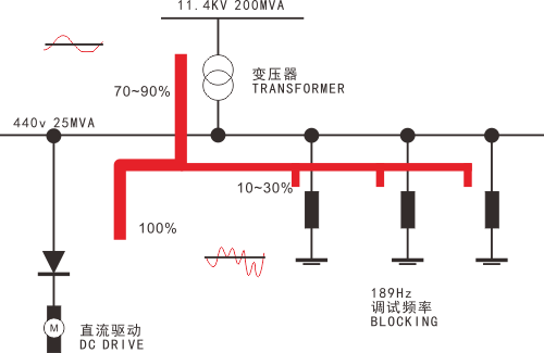
◇Typical steady-state non-linear load as a proportion of total load >10 %, <30%. Tuned filter capacitor banks are required because the equipment generates a small amount of harmonic current.
◇Typical steady-state non-linear loads account for >30% of the total load. Harmonic filters are required due to the large amount of harmonic currents generated by the equipment.
Step 2: Non-linear load form
◇Different types of rectification equipment will produce harmonics of different orders.
Step 3: Determine the number of main harmonics
◇Three-phase rectification equipment Harmonics of the 5th, 7th, 11th, 13th... will be generated, with the 5th and 7th harmonics predominating. This type of equipment is used in large numbers by modern industry, using 6 or 12 pulse full wave rectification, such as frequency converters, DC motors, three-phase UPS, cables, electrolysis, telecommunications, etc.
◇Single-phase rectifier devices Will generate harmonics of the 3rd, 5th, 7th, 9th..., with the 3rd harmonic predominating. This type of equipment is used in large numbers for residential building types, where the equipment is mostly single-phase loads, using 12-pulse rectification devices, such as personal computers, monitors, single-phase UPS, energy-saving lamps.
Step 4: Improvement programme
◇Different equipment produces different harmonics and requires different ways of improvement.
◇Tuned filter capacitor bank, XL = 7% Xc; used to avoid resonance of the 5th harmonic or higher and to safely compensate the power factor.
◇Tuned filter capacitor bank, XL = 14%Xc; used to avoid resonance of the 3rd and higher harmonics and to safely compensate the power factor.
◇Low-voltage rimless harmonic filters effectively absorb most of the harmonic currents and improve the compensation power factor.
◇Low voltage 3rd harmonic filter that reduces both 3-phase and neutral (N phase) harmonic currents and harmonic voltages.
◇Active filters that effectively filter out harmonic currents of all orders from the 2nd to the 52nd.
◇Dynamic power factor compensation system that responds to rapidly changing loads, compensates reactive power in real time, avoids inrush currents and suppresses harmonics.
◇Ordinary capacitor compensation for reactive power compensation with minimal system harmonic distortion.
| Electricity network |
400V 50Hz |
||||||
| Step 1 | Typical steady-state non-linear load to total load ratio〉10%, <30% three-phase rectifier | Typical steady-state non-linear load to total load ratio〉10%, <30% three-phase rectifier | Shock rapid change loads | Few non-linear loads | |||
| Step 2 | Three-phase rectification equipment | Single-phase rectification equipment | Three-phase rectification equipment | Single-phase rectification equipment | Complex harmonic components | Short, frequent work cycles |
THD1﹤5% THD2﹤5%
|
| Step 3 | 5 times 7 times | 3 times | 5 times 7 times | 3 times | 3 times 5 times 4 times 7 times etc. | 5 times 7 times | |
| Step 4 | 7% tuned filter capacitor banks | 14% tuned filter capacitor bank | Passive filters | Third harmonic filter |
Active filters |
Dynamic power factor compensation capacitor banks | General compensation capacitor banks |
Component quick selection table:
| Component type |
400V base wave Output capacity |
Mating capacitors | Mating reactors | Remarks | ||||
| Model | Dimensions mm | Number | Model | Dimensions mm | Number | |||
|
FTCE-480-20.1/7 |
15.0 |
FTAKMJ0.48-20.1-3 |
106*260 |
1 |
FTE0.48-20.1-3/7 |
210*170*190 |
1 |
Anti 5th and 7th harmonic reactive power compensation components (with 7% detuned reactor) |
|
FTCE-480-30.0/7 |
22.4 |
FTAKMJ0.48-30.0-3 |
116*290 |
1 |
FTE0.48-30-3/7 |
230*175*200 |
1 |
|
|
FTCE-480-33.5/7 |
25.0 |
FTAKMJ0.48-33.5-3 |
136*290 |
1 |
FTE0.48-33.5-3/7 |
230*190*200 |
1 |
|
|
FTCE-480-40.2/7 |
30.0 |
FTAKMJ0.48-20.1-3 |
106*260 |
2 |
FTE0.48-40.2-3/7 |
220*190*210 |
1 |
|
|
FTCE-480-50.0/7 |
37.4 |
FTAKMJ0.48-25.0-3 |
116*260 |
2 |
FTE0.48-50.0-3/7 |
260*190*250 |
1 |
|
|
FTCE-480-60.0/7 |
44.8 |
FTAKMJ0.48-30.0-3 |
116*290 |
2 |
FTE0.48-60.0-3/7 |
260*200*250 |
1 |
|
|
FTCE-480-67.0/7 |
50.0 |
FTAKMJ0.48-33.5-3 |
136*290 |
2 |
FTE0.48-33.5-3/7 |
230*190*200 |
2 |
|
|
FTCE-480-80.4/7 |
60.0 |
FTAKMJ0.48-20.1-3 |
106*260 |
4 |
FTE0.48-40.2-3/7 |
220*190*210 |
2 |
|
|
FTCE-480-100.0/7 |
75.0 |
FTAKMJ0.48-25.0-3 |
116*260 |
4 |
FTE0.48-50.0-3/7 |
260*190*250 |
2 |
|
|
|
25.0 |
|
136*290 |
1 |
FTE0.277-11.2-3/7N |
125*143*196 |
3 |
|
|
|
50.0 |
|
136*290 |
2 |
FTE0.277-22.4-3/7N |
125*158*233 |
3 |
|
|
FTCE-525-22.4/13.5 |
15.0 |
FTAKMJ0.525-22.4-3 |
116*260 |
1 |
FTE0.525-22.4-3/13.5 |
250*200*210 |
1 |
Anti-3rd harmonic reactive power compensation component (with 13.5% detuned reactor) |
|
FTCE-525-30.0/13.5 |
20.1 |
FTAKMJ0.525-30.0-3 |
116*290 |
1 |
FTE0.525-30.0-3/13.5 |
280*190*230 |
1 |
|
|
FTCE-525-37.3/13.5 |
25.0 |
FTAKMJ0.525-37.30-3 |
136*290 |
1 |
FTE0.525-37.3-3/13.5 |
290*200*240 |
1 |
|
|
FTCE-525-40.0/13.5 |
26.8 |
FTAKMJ0.525-20.0-3 |
106*260 |
2 |
FTE0.525-40.0-3/13.5 |
290*200*240 |
1 |
|
|
FTCE-525-44.8/13.5 |
30.0 |
FTAKMJ0.525-22.4-3 |
116*260 |
2 |
FTE0.525-44.8-3/13.5 |
290*210*260 |
1 |
|
|
FTCE-525-50.0/13.5 |
33.6 |
FTAKMJ0.525-25.0-3 |
116*260 |
2 |
FTE0.525-25.0-3/13.5 |
250*200*210 |
2 |
|
|
FTCE-525-60.0/13.5 |
40.3 |
FTAKMJ0.525-30.0-3 |
116*290 |
2 |
FTE0.525-30.0-3/13.5 |
280*190*230 |
2 |
|
|
FTCE-525-67.1/13.5 |
45.0 |
FTAKMJ0.525-33.5-3 |
136*290 |
2 |
FTE0.525-33.5-3/13.5 |
290*200*240 |
2 |
|
|
FTCE-525-74.5/13.5 |
50.0 |
FTAKMJ0.525-37.30-3 |
136*290 |
2 |
FTE0.525-37.3-3/13.5 |
290*200*240 |
2 |
|
|
|
25.0 |
|
136*290 |
1 |
FTE0.303-12.4-3/13.5N |
125*160*240 |
3 |
|
|
|
50.0 |
|
136*290 |
2 |
FTE0.303-24.8-3/13.5N |
135*200*270 |
3 |
|
|
Selection notes: FTCE - 480 - 20 / 7 -------- ------- ---- ---- ∣ ∣ ∣ ∣ ∣ ∣ ∣ ∣ ∣ ∣ ∣ ∣ ---------------------- Component configuration reactance (%) ∣ ∣ ∣ ∣ ∣ ∣----------------------------- Configuration capacitor capacity (kvar) ∣ ∣---------------------------------------- Rated voltage (vac) Common complement - line voltage
∣----------------------------------------------- FT-Corporate Code CE-component type
|
|
|
Application example If a project system voltage 400V, the required compensation output capacitance 340kvar (installed capacity 456kvar), three-phase common complement 250, three-phase sub-complement 90, the load is mainly the 5th and 7th harmonics mainly. Reference selection as right: |
FTCE 480-33.5/7*2 FTCE 480-67.0/7*4
Controllers:FTJKW-12 |
Note: Other specifications available on request
-
- Filter assemblies (capacitors + reactors) (FTCE series)
Previous:
Next:
Related Products
Online Consultation
Our products are widely used in fields such as reactive power compensation and filtering systems, power electronics, new energy, and household appliances.
CONTACT
Add: No. 36 Xingmin Road, Hecheng Street, Gaoming District, Foshan City
Tel: 0757-27886317/ 0757-27330976
Fax: 0757-27330975
Web: www.kscap.cn
E-mail: sale@kscap.cn

OFFICIAL ACCOUNT